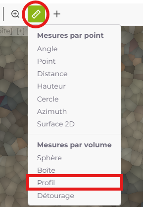
Profile
The Profile tool in RIM-Nat allows you to create a longitudinal section of the model by defining a path within the 3D scene. This tool is especially useful for analyzing elevation changes and generating a 2D elevation view of the selected profile, even along a complex path.
Usage
- Selecting the Tool: Click on the profile icon in the toolbar to activate the tool.
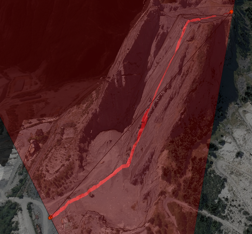
- Placing Points: Use left-clicks in the scene to place points along your profile. The first click sets the starting point; then, add as many points as needed to trace the desired path. The points do not need to be coplanar, as the elevation view will automatically flatten the profile onto an XZ plane.
- Finalizing the Profile: Right-click to complete the profile creation. Each segment will be aligned and projected onto a single 2D plane, allowing the entire profile to be displayed in a single elevation view.
Displaying the Profile in 2D Elevation View
To display the profile in an aligned 2D elevation view:
Selecting the Profile: Select the profile in the scene.
Accessing Properties: In the profile properties panel, click on the chart icon to open the 2D elevation view.
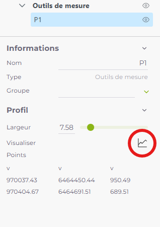
Adjusting the Width: In the properties panel, set the width of the slice to include more or fewer points around the profile line.
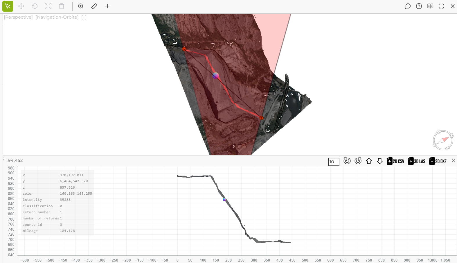
Once activated, the elevation window shows the section of the point cloud contained within the area defined by the profile, based on the chosen width.
Navigation and Options in the 2D Elevation View
The elevation view provides several interactive options and features:
Hovering over the Profile: When hovering over the 2D view, a sphere appears in the 3D scene to indicate the exact 3D location of the hovered point.
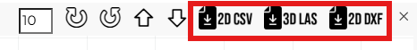
Rotating and Moving the Profile: Use the icons to rotate or move the profile in steps, here set to 10.
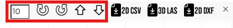
Exporting Data: Three export formats are available:
- 3D CSV: Exports the points in 3D as a CSV file.
- 3D LAS: Exports the points within the profile area as a LAS file.
- 2D DXF: Exports the flattened 2D profile as a DXF file, including point objects arranged as shown in the elevation view.
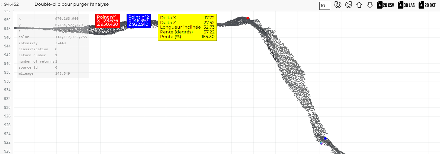
Analysis in the 2D Elevation View
The elevation view also allows for various analyses on the profile, including:
- Slope Measurement: To measure the slope, double-click to set the first point, then double-click again to set the second point. The measurement details include:
- X and Z coordinates of each point.
- Delta X and Delta Z between points.
- Inclined Length between points.
- Slope expressed in degrees and percentage.
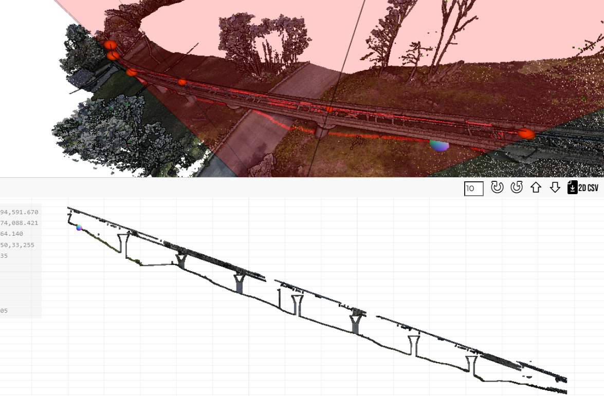
Example of Use: Aligned View for Longitudinal Analyses
This tool allows for complex longitudinal sections, ideal for studying winding paths or extended structures like bridges. The following image shows a flattened profile of a bridge with multiple segments, projected onto a single plane for a detailed elevation view.
Tips for Use
- Viewing Area: Before starting the measurement, ensure you have a clear view of the area you wish to measure.
- Navigation Mode: Since the mouse is generally used for movement, it may be useful to temporarily switch to another navigation mode to enable keyboard navigation while placing profile points with the mouse.
- Deleting: Select an existing measurement and click on the Delete icon in the top toolbar to remove it.